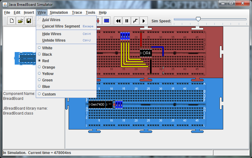
Virtual Breadboard It is a circuit simulator on a virtual breadboard. It supports virtual components like microcontrollers, TTL, graphical and alphanumerical LCDs and others in addition to virtual instruments and certainly the basic components (resistors, capacitors.) Created by James Caska. Freemium $ $ $ Windows. Solderless Breadboard Layout Sheets (plug and Play Electronics): Here's a fun system designed to take care of some of the headaches involved in breadboarding a circuit.It is is a simple set of template files drawn to scale with real world electronic components. Using a vector drawing program you simply move the c. The simulator shows a graphic of a Pi wired to a combined humidity, temperature, pressure sensor and a red LED via a breadboard, a plug board that allows circuits to be wired together rapidly. Download Virtual Breadboard 4.4 free latest version offline setup for Windows 64-bit. Virtual Breadboard (VBB) 4.4 is a powerful solution for Breadboard Integrated Circuits simulation as well as work for microcontrollers development.
Using the Live 3D Breadboard tool in TINA, you can automatically build a life-like 3D picture of a solderless breadboard.
When you run TINA in interactive mode, components like switches, LEDs, instruments, etc. become “live” and will work on the virtual breadboard just as in reality.
You can use this capability of TINA to prepare and document lab experiments.
You can either assemble the circuit step-by-step or by generating the whole circuit on the breadboard.
Pick up and move parts on the breadboard using the mouse, and TINA will automatically rearrange the wiring while retaining connectivity.
In the same fashion, you can select and move wires for clearer appearance.

Note that you cannot change the endpoints of a wire this way–wiring integrity is preserved.
The breadboard tool is mostly intended for educational purposes to prepare laboratory experiments in a safe 3D environment.
You can also use this tool to guide you in actually wiring a PCB board for lab verification, with the 3D viewer available the PCB Designer of TINA.
If you turn the PCB upside down (by holding down the left mouse button over an unused area and moving the mouse), you can see the connections of the wires from the PCB solder side to the oscilloscope.
Breadboard Simulator Free Online
If you use connectors instead of soldering wires directly to the PCB, you can connect the instruments through those.
Breadboard Simulator Free Download
By adding Header2 and Header3 (they can be found under the Connectors button on the Switches component toolbar), you can make the interconnection shown on the picture.